Programming the CAN Board
The CAN board that will be connected to the PC needs to be programmed with the provided USB_CAN.hex program. The program establishes a USB connec- tion through the emulation of a virtual COM port. Open AVR Studio without opening an existing or new project. Choose Tools’Program AVR’Connect and select the programming adapter (e.g. AVRISP mkII) and the interface (e.g., USB).
Figure 1.7: AVR-Studio
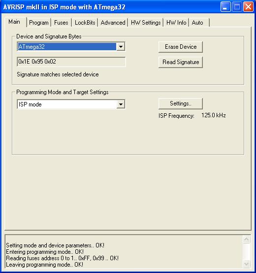
Under Main choose Atmega32 and click on the button Read Signature. If the chip was recognized by AVR Studio, the text Signature matches selected device appears. Programming Mode is ISP mode, ISP frequency 125.0 kHz.
Figure 1.8: ISP Mode
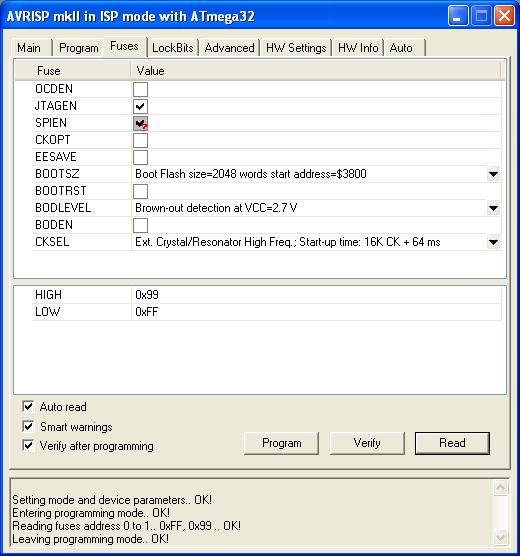
Under Fuses, tick the boxes for JTAGEN and SPIEN to enable JTAG and SPI programming, respectively. Choose Ext. Crystal/Resonator High Frequency.
16KCK + 64ms
Code (1.1)
If the fuse bits are set according to the screenshot, the HIGH and LOW bytes should read 0x99 and 0xFF, respectively. Click the button Program to set the fuse bits on the Atmega32. You can check the fuse bits by clicking the button Verify.
Figure 1.9: Fuse Bits
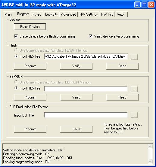
Under Program, tick the boxes Erase divide before flash programming and Ver- ify device after programing. Select the USB_CAN.hex as input hex file for flash programming
Figure 1.10: Programming


