This is an old revision of the document!
Table of Contents
Global Navigation Satellite Systems GNSS
Introduction to the GNSS
Global Navigation Satellite Systems (short GNSS) are useful to position an object (here drone) in 3D space, mostly outdoors.
Actually, 2D, planar (longitude/latitude) positioning is quite good and in most applications suitable, vertical positioning used to be inaccurate, so most drones use a different strategy to check their altitude, mostly measuring atmospheric pressure changes (using barometer). UAVs usually operate on long distances (some meter to even thousands of kilometres) so satellite-based positioning seems to be a reasonable choice. As receivers became cheaper, they appeared in almost all drones that operate in autonomous mode and in many of those that are manually controlled, to smoothen operations, provide rescue features (i.e. Return to Home function) to ensure basic and advanced features like i.e. geofencing, collision avoidance and so on.
Current, modern GNSS receivers operate with multiple constellations parallel, delivering even better accuracy of the planar positioning. Still to get reliable positioning with high accuracy, one needs to ensure good satellite visibility.
There is a number of factors, decreasing positioning that every UAV operator should be aware.
There is a number of factors, decreasing positioning that every UAV operator should be aware, as they may lead to incidents and accidents:
- Time synchronisation - it is crucial to have common time-base for both sender and receiver. Time synchronisation occurs during so-called “obtaining fix” and in short is based on error minimisation between position estimation based on at least four (usually much more) satellites. Time synchronisation is also performed periodically, as satellite time-base is considered as a reference one but receiver implementation varies in quality. Thus you may observe periodical degradation of the accuracy in reference conditions, because of the de-synchronisation of the receiver.
- Selected Availability (SA) - as introduced by the constellation owner to interfere radio signal of the satellites, thus decrease the accuracy the controlled way. This was widely used in case of the American GPS (Navstar) until the first war in the Persian Gulf when US Army had to switch to the commercial receivers (affected by SA) because of lacks of delivery of the military products (that had SA corrected internally). Since then, GPS positioning became much more useful because of the increased accuracy of the positioning, once SA was disabled or at least reduced.
- Ionosphere delay - as solar radiation has a strong impact on the ionic sphere of the Earth, radio signal passing through it may experience deflection (thus delays). That is the second, natural phenomena, decreasing accuracy. Solar radiation is given by the KP Index that can be read close to realtime and is related to solar activity. With KP over 3, flying UAV is not advised, or at least try to avoid flying in a tight environment when filming i.e. northern lights as you may experience sudden shifts of your drone even some dozen of meters. You can read the current KP index and forecast i.e. here: Aurora Service.
- Troposphere - has some minor impact (comparing to the mentioned above) yet it does exist. The troposphere is relatively thin, comparing i.e. to the ionosphere. Advanced GPS receivers may use a built-in calendar to provide thermal compensation, based on the time and current position as using average temperature for the obtained location.
- Ephemeris error - sometimes, satellite orbit is altered and satellite is not where it is intended to be, so the distance between satellite and receiver is affected. GPS receiver is unaware of the position deviation, thus it has an impact on the positioning accuracy.
Some of those phenomena can be handled tricky way (i.e. ionosphere deflection impacts different way signals with different frequency thus Glonass system can handle this issue almost real-time by calculating error, differential-based way) while others can be applied post-factum or live using corrections sent via other channels.
The detailed description of the impact of the aforementioned factors for accuracy and performance is presented below in section GNSS Performance and Accuracy.
GNSS History
US GPS NAVSTAR

- The United States Navy conducted satellite navigation experiments in the mid-1960s to track US submarines carrying nuclear missiles. With six satellites orbiting the poles, submarines were able to observe the satellite changes in Doppler and pinpoint the submarine's location within a matter of minutes.
- In the early 1970s, the Department of Defense (DoD) wanted to ensure a robust, stable satellite navigation system would be available. Embracing previous ideas from Navy scientists, the DoD decided to use satellites to support their proposed navigation system. DoD then followed through and launched its first Navigation System with Timing and Ranging (NAVSTAR) satellite in 1978.
- The 24 satellite system became fully operational in 1993. When selective availability was lifted in 2000, GPS had about a five-meter (16 ft) accuracy.
- The latest stage of accuracy enhancement uses the L5 band and is now fully deployed. GPS receivers released in 2018 that use the L5 band can have much higher accuracy, pinpointing to within 30 centimetres or 11.8 inches.

RF GLONASS

- The first proposal to use satellites for navigation was made by V.S.Shebashevich in 1957. This idea was born during the investigation of the possible application of radio-astronomy technologies for aeronavigation. Further investigations were conducted in a number of the Soviet institutions to increase the accuracy of navigation definitions, global support, daily application and independence from weather conditions. The research results were used in 1963 for an R&D project on the first Soviet low-orbit “Cicada” system.
- In 1967 the first navigation Soviet satellite “Cosmos-192” was launched. The navigation satellite provided continuous radio navigation signal transmission on 150 and 400 MHz during its active lifetime.
- he “Cicada” system of four satellites was commissioned in 1979. The GLONASS system was formally declared operational in 1993. In 1995 it was brought to a fully operational constellation (24 GLONASS satellites of the first generation).
- In 2008 “Cicada” and “Cicada-M” users started to use GLONASS system and the operation of those systems was halted. It was impossible for the low-orbit systems to meet the requirements of a great number of users.

EU GALILEO

- The first Galileo test satellite, the GIOVE-A, was launched 28 December 2005, while the first satellite to be part of the operational system was launched on 21 October 2011.
- As of July 2018, 26 of the planned 30 active satellites are in orbit. Galileo started offering Early Operational Capability (EOC) on 15 December 2016, providing initial services with a weak signal and is expected to reach Full Operational Capability (FOC) in 2019.
- The complete 30-satellite Galileo system (24 operational and 6 active spares) is expected by 2020.
- It is expected that the next generation of satellites will begin to become operational by 2025 to replace older equipment. Older systems can then be used for backup capabilities.

CHINA BeiDou (BDS)

- It consists of two separate satellite constellations. The first BeiDou system, officially called the BeiDou Satellite Navigation Experimental System and also known as BeiDou-1, consists of three satellites which since 2000 has offered limited coverage and navigation services, mainly for users in China and neighbouring regions. Beidou-1 was decommissioned at the end of 2012.
- The second generation of the system, officially called the BeiDou Navigation Satellite System (BDS) and also known as COMPASS or BeiDou-2, became operational in China in December 2011 with a partial constellation of 10 satellites in orbit.
- Since December 2012, it has been offering services to customers in the Asia-Pacific region.
- On December 27, 2018, Beidou-3 officially began to provide global services.

GNSS SEGMENTS
GNSS satellite systems consist of three major components or “segments”: space segment, control segment and user segment.
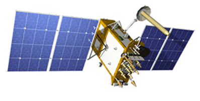
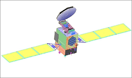
Space Segment The space segment consists of GNSS satellites, orbiting about 20,000 km above the earth. Each GNSS has its own “constellation” of satellites, arranged in orbits to provide the desired coverage. Each satellite in a GNSS constellation broadcasts a signal that identifies it and provides its time, orbit and status.
Control Segment The control segment comprises a ground-based network of master control stations, data uploading stations and monitor stations; in the case of GPS, two master control stations (one primary and one backup), four data uploading stations and 16 monitor stations, located throughout the world. In each GNSS system, the master control station adjusts the satellites’ orbit parameters and onboard high-precision clocks when necessary to maintain accuracy. Monitor stations, usually installed over a broad geographic area, monitor the satellites’ signals and status and relay this information to the master control station. The master control station analyses the signals then transmits orbit and time corrections to the satellites through data uploading stations.
User Segment The user segment consists of equipment that processes the received signals from the GNSS satellites and uses them to derive and apply location and time information. The equipment ranges from smartphones and handheld receivers to sophisticated, specialized receivers used for high-end survey and mapping applications.
GNSS Antennas GNSS antennas receive the radio signals that are transmitted by the GNSS satellites and send these signals to the receivers. GNSS antennas are available in a range of shapes, sizes and performances. The antenna is selected based on the application. While a large antenna may be appropriate for a base station, a lightweight, low-profile aerodynamic antenna may be more suitable for aircraft or Unmanned Aerial Vehicles (UAV) installations. Figure 8 presents a sampling of GNSS antennas.
GNSS Receivers Receivers process the satellite signals recovered by the antenna to calculate position and time. Receivers may be designed to use signals from one GNSS constellation or from more than one GNSS constellation. Receivers are available in many form factors and configurations to meet the requirements of the varied applications of GNSS.
GNSS Augmentation Positioning based on standalone GNSS service is accurate to within a few metres. The accuracy of standalone GNSS, and the number of available satellites, may not be adequate for the needs of some users. Techniques and equipment have been developed to improve the accuracy and availability of GNSS position and time information.

GPS terrestrial segment

- 33 in-orbit spacecraft,
- Operator AFSPC,
- Type military, civilian,
- Orbital altitude: 20,180 km,
- 6 orbital planes MEO,
- Satellite lifetime: 10 years,
- Satellite mass: 1080 kg,
- Satellite body dimensions: 1,9 m × 1.93 m × 1.52 m,
- Accuracy 500-30 cm,
- Coverage Global,
GLONASS terrestrial segment
- 26 in-orbit spacecrafts,
- Operator Roskosmos,
- Type military, civilian,
- Orbital altitude: 19 130 km,
- 3 orbital planes MEO,
- Satellite lifetime: 10 years
- Satellite mass: 1450 kg,
- Accuracy 2.8-7.38 m
- Coverage Global
Galileo terrestrial segment

- 30 in-orbit spacecrafts
- Operator GSA, ESA
- Type civilian, commercial,
- Orbital altitude: 23,222 km,
- 3 orbital planes MEO,
- Satellite lifetime: >12 years
- Satellite mass: 675 kg
- Satellite body dimensions: 2.7 m × 1.2 m × 1.1 m
- Span of solar arrays: 18.7 m,
- Power of solar arrays: 1.5 kW,
- Accuracy 1 m (public), 1 cm (encrypted),
- Coverage Global
BeiDou terrestrial segment
- 33 in-orbit spacecrafts
- Operator CNSA,
- Type military, commercial,
- Orbital altitude: 23,222 km,
- Orbital planes MEO, IGSO, GEO
- Satellite lifetime: >12 years
- Satellite mass: 675 kg,
- Accuracy 10 m (public) 10 cm (encrypted),
- Coverage Global
GNSS systems comparison
All modern and operating GNSS systems like GPS, GLONASS, Galileo or BeiDou which were developed by different countries and organizations use terrestrial segment containing satellites orbiting over the Earth. Each satellite constellation occupies their own unique orbit segments. The entire view of GNSS constellation is present in the picture above. Modern positioning and timing modules have evolved to take advantage of multiple GNSS constellations at once. Combining multiple satellite systems improves the availability of signals, gives operators more access and increases accuracy.

GPS Signals
The generated signals onboard the satellites are based or derived from generation of a fundamental frequency ƒo=10.23 MHZ. The signal is controlled by an atomic clock and has stability in the range of 10−13 over one day. Two carrier signals in the L-band, denoted L1 and L2, are generated by integer multiplications of ƒo. The carriers L1 and L2 are biphase modulated by codes to provide satellite clock readings to the receiver and transmit information such as the orbital parameters. The codes consist of a sequence with the states +1 or -1, corresponding to the binary values 0 or 1. It contains information on the satellite orbits, orbit perturbations, GPS time, satellite clock, ionospheric parameters, and system status messages. The modulation of L1 by Pcode, C/A-code and navigation message (D), is done using the quadrature phase-shift keying (QPSK) scheme. The C/A-code is placed on the LI carrier with 90° offset from the P-code since they have the same bit transition epochs. For the L1 and L2 we have:
L1(t) = a1P(t)W(t)cos(2πf1t)+a1C/A(t)D(t)sin(2πf1t)
L2(t) = a2P(t)W(t)cos(2πf2t)

GPS signals in Space The signal broadcast by the satellite is a spread spectrum signal, which makes it less prone to jamming. The basic concept of the spread spectrum technique is that the information waveform with small bandwidth is converted by modulating it with a large-bandwidth waveform. The navigation message consists of 25 frames with each frame containing 1500 bit and each frame is subdivided into 5 sub-frames with 300 bit. The information transmitted by the navigation message is periodically updated by the control segment. It is well known that the presence of dual-frequency measurements (L1 and L2) has good advantages to eliminate the effect of the ionosphere and enhance the ambiguity resolution, especially for the high precision measurements.

Glonass signals
Glonass transmit C/A-code on L1, P-code on L1 and L2. Glonass observables (code and phase) are similar to GPS. The main difference between GPS and GLONASS is that GLONASS uses Frequency Division Multiple Access (FDMA) technology to discriminate the signals of different satellites, but GPS and Galileo use (Code Division Multiple Access, CDMA) to distinguish between the satellites. All Glonass satellites transmit the same C/A- and P-codes, but each satellite has slightly different carrier frequencies.
𝑓_1^𝑛 = 1602+0.5625.n MHz
𝑓_2^𝑛  = 1246+0.4375.n MHz
		with
(𝑓_1^𝑛)/(𝑓_2^𝑛 )=9/7
where n is the frequency channel number 1 ≤ n ≤ 24 , covering a frequency range in L1 from 1602.5625MHz to 1615.5MHz.
- The navigation message is contained in so-called sub frames, which have duration of 2.5 minutes.
- Each sub frame consists of five frames with a duration of 30 seconds.
- The navigation message contains information, similar to GPS navigation message, about the satellite orbits, their clocks, among others.

Galileo signals
Galileo provides several navigation signals in right-hand circular polarization (RHCP) in the frequency ranges of 1164–1215 MHz (E5a and E5b), 1260–1300 MHz (E6) and 1559–1592 MHz (E2-L1-E1) that are part of the Radio Navigation Satellite Service (RNSS) allocation. All Galileo satellites share the same nominal frequency, making use of code division multiple access (CDMA) techniques. Galileo uses a different modulation scheme for its signals, the binary offset carrier (BOC) and quadrature-phase skip keying (QPSK).


BeiDou signals
BeiDou transmits navigation signals in three frequency bands: B1, B2, and B3, which are in the same area of L-band as other GNSS signals. To benefit from the signal interoperability of BeiDou with Galileo and GPS China announced the migration of its civil B1 signal from 1561.098 MHz to a frequency centred at 1575.42 MHz — the same as the GPS L1 and Galileo E1 civil signals — and its transformation from a quadrature phase-shift keying (QPSK) modulation to a multiplexed binary offset carrier (MBOC) modulation similar to the future GPS L1C and Galileo’s E1.

GNSS signal processing
The main function of the signal processor in the receiver is the reconstruction of the carriers and extraction of codes and navigation messages. After this stage, the receiver performs the Doppler shift measurement by comparing the received signal by a reference signal generated by the receiver. Due to the motion of the satellite, the received signal is Doppler shifted. The code ranges are determined in the delay lock loop (DLL) by using code correlation. The correlation technique provides all components of bi-modulated signals. The correlation technique is performed between the generated reference signal and the received one. The signals are shifted with respect to time so that they are optimally matched based on mathematical correlation. The GNSS receiver could be designed to track the different GNSS signals and could be of many types:
- The first type could process all GNSS signals GPS L1, L2, L5 and Galileo OS, CS using L1, E5 and E6 and also Glonass L1 and L2.
- The second type uses free signal and codes, GPS L1 and L2C and Galileo OS, on L1 and E5.
- The third type uses L1 and E5.
- Forth type uses GPS L1 and L2 (which are already in the market).
- Fifth type uses GPS and Glonass signals (which already exist).

GNSS differential position
There is an increased interest in differential positioning due to the numerous advantages of wireless communications and networks. Most of the errors that affect GNSS are common between the receivers, which observe the same set of satellites. Thus, by making differential measurement between two or more receivers, most of these errors could be cancelled. The basic concept of differential position is the calculation of position correction or range correction at the reference receiver and then sending this correction to the other receiver via radio link.

GNSS Wide Area Augmentation System (WAAS)
Wide Area Augmentation System (WAAS) is a new augmentation to the United States Department of Defense’s (DoD) Global Positioning System (GPS) that is designed to enhance the integrity and accuracy of the basic GPS capability. The WAAS uses geostationary satellites to receive data measured from many ground stations, and it sends information to GPS users for position correction. Since WAAS satellites are of the geostationary type, the Doppler frequency caused by their motion is very small. Thus, the signal transmitted by the WAAS can be used to calibrate the sampling frequency in a GPS receiver. The WAAS signal frequency is at 1575.42 MHz. The WAAS services are available on both L1 and L5.

GNSS Correction Systems
Selection of the appropriate augmentation method or correction service depends on the performance required for vehicle or aircraft navigation software. There are essentially four levels of positioning: standalone uncorrected; positioning derived from publicly available correction services such as the WAAS network in North America or Europe’s EGNOS system; positioning solutions derived from globally available subscription-based L-band services; and regional/ local RTK network solutions.
Standalone uncorrected and WAAS/EGNOS type solutions provide position accuracy ranging from 1-10 metres. On the other end of the scale, RTK correction networks provide the most accurate centimetre-level solutions. While L-band solutions deliver corrections directly to the GNSS receiver via satellite, RTK solutions require a base station and a radio to get the corrections needed, limiting operator flexibility and increasing total system cost and complexity.
With subscription-based L-band correction services, users receive Precise Point Positioning (PPP) corrections to help mitigate and remove measurement errors and position jumps. PPP solutions utilize modeling and correction products including precise satellite clock and orbit data to enhance accuracy.

GNSS EGNOS
The European Geostationary Navigation Overlay Service (EGNOS) is being developed by the European Space Agency (ESA), for the Safety of Air Navigation (Eurocontrol). EGNOS will complement the GNSS systems. It consists of three transponders installed in geostationary satellites and a ground network of 34 positioning stations and four control centres, all interconnected. EGNOS as WAAS broadcast the differential corrections to the GNSS users through Geostationary satellites, in the European region and beyond.


Entire EGNOS system contain Ground Segment, Space Segment, Support segment, Space Segment and User Segment
Ground segment
A network of 40 Ranging Integrity Monitoring Stations (RIMS), 2 Mission Control Centres (MCC), 6 Navigation Land Earth Stations (NLES), and the EGNOS Wide Area Network (EWAN), which provides the communication network for all the components of the ground segment.
- 40 RIMS: the main function of the RIMS is to collect measurements from GPS satellites and transmit these raw data each second to the Central Processing Facilities (CPF) of each MCC. The configuration used for the initial EGNOS OS includes 40 RIMS sites located over a wide geographical area.
- 2 MCC: receive the information from the RIMS and generate correction messages to improve satellite signal accuracy and information messages on the status of the satellites (integrity). The MCC acts as the EGNOS system’s 'brain'.
- 6 NLES: the NLESs (two for each GEO for redundancy purposes) transmit the EGNOS message received from the central processing facility to the GEO satellites for broadcasting to users and to ensure the synchronisation with the GPS signal.

Support segment
In addition to the stations/centres, the system has other ground support installations that perform the activities of system operations planning and performance assessment, namely the Performance Assessment and Checkout Facility (PACF) and the Application Specific Qualification Facility (ASQF) which are operated by the EGNOS Service Provider (ESSP).
- PACF: provides support to EGNOS management in such area as performance analysis, troubleshooting and operational procedures, as well as upgrade of specification and validation, and support to maintenance.
- ASQF: provides civil aviation and aeronautical certification authorities with the tools to qualify, validate and certify the different EGNOS applications.
Space Segment
Composed of three geostationary satellites broadcasting corrections and integrity information for GPS satellites in the L1 frequency band (1575,42 MHz). This space segment configuration provides a high level of redundancy over the whole service area in case of a geostationary satellite link failure. EGNOS operations are handled in such a way that, at any point in time, at least two of the three GEOs broadcast an operational signal.

User Segment
The EGNOS User segment is comprised of EGNOS receivers that enable their users to accurately compute their positions with integrity. To receive EGNOS signals, the end-user must use an EGNOS-compatible receiver. Currently, EGNOS compatible receivers are available for such market segments as agriculture, aviation, maritime, rail, mapping/surveying, road a location-based service (LBS).
GNSS RTK Network
RTK network concept is similar to the WADGNSS but the reference stations are generally distributed over a regional area and the network control centre is responsible for transmitting the phase measurement correction to the GNSS user (rover receiver). Mobile wireless networks are generally used in this type of applications due to the need for duplex communication where the rover receiver should send initially the approximate position to the network processing centre. The network processing centre computes VRS observations and sends it to the user. The number of reference stations in the single RTK approach is 30 stations in 10,000 km2.

GNSS Performance and Accuracy
Four parameters are used to characterize GNSS performance which is based on the RNP specification:
- Accuracy: The accuracy of an estimated or measured position of a craft (vehicle, aircraft, or vessel) at a given time is the degree of conformance of that position with the true position, velocity and/or time of the craft. Since accuracy is a statistical measure of performance, a statement of navigation system accuracy is meaningless unless it includes a statement of the uncertainty in a position that applies.
- Availability: The availability of a navigation system is the percentage of time that the services of the system are usable by the navigator. Availability is an indication of the ability of the system to provide usable service within the specified coverage area. Signal availability is the percentage of time that navigation signals transmitted from external sources are available for use. It is a function of both the physical characteristics of the environment and the technical capabilities of the transmitter facilities.
- Continuity: The continuity of a system is the ability of the total system (comprising all elements necessary to maintain craft position within the defined area) to perform its function without interruption during the intended operation. More specifically, continuity is the probability that the specified system performance will be maintained for the duration of a phase of operation, presuming that the system was available at the beginning of that phase of operation.
- Integrity: Integrity is the measure of the trust that can be placed in the correctness of the information supplied by a navigation system. Integrity includes the ability of the system to provide timely warnings to users when the system should not be used for navigation.
The basic idea of GNSS systems is establishing a satellite network in which each satellite sends a signal at a defined time to receivers. The distance from the satellite to the receiver can be calculated, by measuring the time difference from the transmitter to receiver. Using at least 4 satellites simultaneous the 3D Position of the receiver (vertical and horizontal) can be calculated if the position of each satellite is known. The accuracy of GNSS Systems is influenced by the realization of the needed infrastructure causing the influences on the transmitted signals that make the position calculation possible. Satellites used for GNSS Systems are moving at approx. 4 km per seconds (with respect to the earth) under varying conditions. Due to the movement of the receiver and the transmitter, there is the need to take a look at the factors that determine the accuracy of GNSS Systems.
The positioning accuracy depends on many factors. Position and time error given by GPS receivers are influenced by:
- Ionospheric delay - disturbances in the speed of propagation of signals from satellites in the ionosphere (error about 7 m),
- Tropospheric delay - an analogous phenomenon in the troposphere caused by changes in humidity, temperature and air pressure (± 0.5 m),
- Ephemeris error - differences between the theoretical and actual position of the satellites (± 2.5 m),
- satellite clock inaccuracy (± 2 m),
- receiving reflected signals that reach the receiver by other routes than directly from the satellite (± 1 m),
- Receiver errors - noise disrupting the transmission, inaccuracies in the calculation procedures in the software (± 1 m).
- US Department of Defense deliberate action. In order to reduce the accuracy of GPS receivers, disturbances known as Selective Availability (SA) were introduced into the C/A signal. GPS receivers were able to reduce SA interference. However, these disorders were turned off on May 1, 2000, and remained turned off after September 11, 2001.
The idea of Geometric DOP is to state how errors in the measurement will affect the final state estimation. This can be defined as:
GDOP = Δ(Output Location) / Δ(Measured Data)
The low DOP value represents a better positional precision due to the wider angular separation between the satellites used to calculate a unit's position. Other factors that can increase the effective DOP are obstructions such as nearby mountains or buildings.
DOP can be expressed as a number of separate measurements:
- HDOP – horizontal dilution of precision
- VDOP – vertical dilution of precision
- PDOP – position (3D) dilution of precision
- TDOP – time dilution of precision
- GDOP – geometric dilution of precision
Sample EGNOS Dilution Of Precision (HDOP) shows picture above:

GNSS Ionospheric signal propagation over a region shows another picture above:

EDCN Introduction
EGNOS Data Collection Network (EDCN) was created in 2001, to acquire experience but also develop procedures on how to assess and validate the performance provided by augmentation systems like EGNOS. This data collection network is composed of multiple stations hosted often at Universities, and it is complemented by the contributions from Air Navigation Service Providers interested on certifying and providing SBAS services in their national air space (among others AENA Spain, DTI/DSNA France, NATS UK, ENAV Italy, NAV Portugal, Skyguide Switzerland, PANSA Poland). All collected data is managed by EUROCONTROL in France, in charge not only of developing all the software used to process the data defined in the avionics standards, but also the definition of procedures and accumulation of results to present them in a coherent manner to the Regulator body in charge of the ESSP certification as EGNOS Operator.
EDCN Components
- GNSS satellite constellations – GPS NAVSTAR, GLONAS, Galileo,
- EGNOS satellites – Inmarsat IOR-W,AOR-E,Artemis
- GNSS ground mounted receivers (NavTech, Septentrio, etc.)
- PC computers, LAN, WAN – Internet,
- Software – PEGASUS powered by EUROCONTROL
- Central Database,


EGNOS availability maps
- 100% >= Availability >= 99% : blue
- 99% > Availability >= 98% : green
- 98% > Availability >= 95% : yellow
- Availability < 95% : red

EGNOS Signal Continuity
Availability EGNOS SIS signal for PRN120 sattelite.

There was no SIS broadcast during 23rd and 24th July 2011, for further details see July Performance Report available at ESSP web page

GNSS Receiver hardware chips
Autonomous UAV usually rely on a GPS position signal which, combined with inertial measurement unit (IMU) data, provides highly precise information that can be implemented for control purposes. In order to avoid accidents in an area heavily populated by other UAV or manned vehicles, it is necessary to know exactly where the UAV is located at all times. Equipped with GPS, a UAV can not only provide location and altitude information but necessary vertical and horizontal protection levels. Typical GNSS receivers which can be easily used in the UAV platforms are listed below.
Multi-GNSS Receiver Module Model GN-87
GN-8720is a stand-alone, complete GNSS receiver module that can provide accurate GNSS PVT (Position, Velocity & Time) information through the serial communication channel. The key device inside is eRideOPUS 7, the latest monolithic GNSS receiver chip that contains ARM9 processor for signal tracking and processing, high performance integrated LNA, PLL Synthesizer, Down-converter, ADC and DSP. GN-8720 also contains Flash ROM for firmware and data storage, TCXO for reference clock, 32kHz crystal for RTC (Real-time clock), L1 band SAW filter and power-on reset circuit. Main features are as follows:
- Supports GPS, GLONASS, SBAS, QZSSand Galileo,
- Outputs a time pulse (1PPS) synchronized to UTC time,
- Software upgrade capability by Flash ROM,
- Active Anti-jamming capability to suppress effects of CW jammers,
- Multipath mitigation effects,
- Works in both Autonomous mode and Assisted mode,
- GPS/GLONASS high indoor sensitivity,
- Fast TTFF of typically <1 second when in hot and 30seconds in warm and 33 seconds in cold start conditions,
- Available of an active and passive antenna,
- Unordered List ItemLow profile, small SMT package reducing the mounting area and mounting cost,

ACEINNA OpenRTK330L
ACEINNA’s OpenRTK330L includes a triple-band RTK/GNSS receiver coupled with redundant inertial sensor arrays to provide cm-level accuracy, enhanced reliability, and superior performance during GNSS outages. The OpenRTK330L integrates a very precise 2 Degree/Hour IMU to offer ten to thirty seconds of high accuracy localization during full GNSS denial. This enables autonomous system developers to safely deliver highly accurate localization and position capabilities in their vehicles at prices that meet their budgets. OpenRTK330L’s embedded Ethernet interface allows easy and direct connection to GNSS correction networks around the world. OpenRTK330L’s CAN bus interface allows simple integration into existing vehicle architectures. The multi-band GNSS receiver can monitor all global constellations (GPS, GLONASS, BeiDou, Galileo, QZSS, NAVIC, SBAS) and simultaneously track up to 80 channels. The module has RF and baseband support for the L1, L2, and L5 GPS bands and their international constellation signal equivalents.

BCM47755
The BCM47755 supports two frequencies (L1+L5), achieves lane-level accuracy outdoors and much higher resistance to multipath and reflected signals in urban scenarios, as well as higher interference and jamming immunity. The BCM47755 incorporates numerous technologies that enable ultralow power consumption in both the location function and the sensor hub function. The device features a low-power RF path, a Big/Little CPU configuration composed of an ARM-based 32-bit Cortex-M4F (CM4), an ARM-based Cortex-M0 (CM0), and is built in a 28 nm process. The BCM47755 can simultaneously receive the following signals:
- GPS L1 C/A
- GLONASS L1
- BeiDou (BDS) B1
- QZSS L1
- Galileo (GAL) E1
- GPS L5
- Galileo E5a
- QZSS L5

UBLOX NEO-M9N module
The NEO-M9N module is built on the robust u-Blox M9 GNSS chip, which provides exceptional sensitivity and acquisition times for all L1 GNSS systems. The u-Blox M9 standard precision GNSS platform, which delivers meter-level accuracy, succeeds the well-known u-Blox M8 product range. NEO-M9N supports concurrent reception of four GNSS. The high number of visible satellites enables the receiver to select the best signals. This maximizes the position accuracy, in particular under challenging conditions such as in deep urban canyons. NEO-M9N detects jamming and spoofing events and reports them to the host so that the system can react to such events. Advanced filtering algorithms mitigate the impact of RF interference and jamming, thus enabling the product to operate as intended. A SAW filter combined with an LNA in the RF path is integrated into the NEO-M9N module. This setup allows normal operation even under strong RF interferences, for example when a cellular modem is co-located with NEO-M9N. NEO-M9N offers backwards pin-to-pin compatibility with previous u-Blox generations, which saves designers time and cost when upgrading their design. Software migration requires little effort thanks to the continuous support of UBX messages across product generations.

UAV designed GNSS Receiver modules
The UAV industry requires lightweight heavy-duty fully IP69K or IP67 waterproof and low power GNSS receiver modules. The sample list of useful UAV GNSS receiver modules which uses different popular GNSS receiver hardware chips are listed below:
Radiolink TS100 Mini GPS Module for Mini PIX Flight Controller
The Radiolink TS100 Mini GPS Module for Mini PIX Flight Controller can measure with a 50-centimetre precision of accuracy when working with concurrent GNSS. The prc-lNA low loss circuit design has enhanced ability to capture extremely weak signals. The TS100 can seize very weak signals and effective suppression of input interference at the same time.
Description
- Positioning 20 satellites in 6 seconds at open ground and valley station-keeping ability
- Reception of GPS/QZSS LI C/A, GLONASS HOf, BelDou Bl SBASll C/AWAAS, EGNOS, MSAS
- Radiolink TS100 Mini GPS Module for Mini PIX Flight Controller
- Features an M8N GPS decoder chip, with u-Blox UBX-M8030 (M8), 72-channel
- Max update rate: up to 10Hz
- Compatible with: Radiolink Mini PIX
Specification
- Positional accuracy: 50-centimeter precision GNSS
- Velocity precision: 0.1m/s
- Max height: 50000m
- Max speed: 515m/s
- Max acceleration: 4G
- Max update rate: up to 10Hz
Sensitivity
- Tracking and Nav.: -167dBm, Reacquisition: -163dBm
- Cold start: -151dBm, Hot start: -159dBm
- Time to first fix: Cold start: 26s, Hot start: 1s
Connect ports
- Power supply: voltage 5VDC+-5 percent, current 50-55mA
Ports
- GPS UART interface
- Baud rate: 1.2K/4.8K/9.6K/19.2K/38.4K/57.6K/112.5K
- Geomagnetic I2C interface
configuration
- Geomagnetic: QMC5883L which with the same technology as HMC5983 form
- Antenna: 2.5dbI high gain and selectivity ceramic antenna
- Double filter: SAWF(Surface acoustic wave filter) form Murata
Dimensions
- 3.20 x 3.00 x 1.20 cm / 1.26 x 1.18 x 0.47 inches
- Weight: 0.0200 kg

Here 2 GNSS module for Pixhawk 2.1
Description
- Here 2 GNSS for Pixhawk 2.1
- Sensitivity: Tracking and Navigation-167dBm, Hot start- 148dBm, Cold start- 157dBm
- Active antenna and passive antenna
- 72-channel u-blox M8N engine GPS/QZSS L1C/A, GLONASSL10F BeiDou B11, etc.
- Navigation update rate: Max 10Hz
Specification
- Processor: STM32F302
- Compass Gyro Accelerometer: ICM20948
- Barometer: MS5611
- Receive type: 72-channel u-blox M8N engine GPS/QZSS L1C/A, GLONASSL10F BeiDou B11, Galileo E1B/C SBAS L1 C/A: WAAS, EGNOS, MSAS, GAGAN
- Navigation update rate: Max 10Hz
- Positioning Accuracy: 3D FIX
- Time to first fix: Cold start 26S, Aided start 2S, Reacquisition 1S
- Sensitivity: Tracking and Navigation-167dBm, Hot start- 148dBm, Cold start- 157dBm
- Assisted GNSS: Assist Now GNSS Online, AssistNow GNSS Offline (up to 35 days), AssistNow Autonomous (up to 6 days) OMA SUPL& 3GPP compliant
- Oscillator: TCXO(NEO-M8N/Q)
- RTC Crystal: Built in
- ROM: Flash(NEO-M8N)
- Available Antennas: Active antenna and passive antenna
- Signal Integrity: Signature feature with SHA 256
Ports
- UART/12C/CAN: JST_GH Main interface, Switch Internally
- STM32 Main programming interface: JST_SUR
Dimensions
- 76mm x 76mm x 16.6mm
- Weight: 49g

Radiolink SE100 GPS Module for PixHawk
Description
- 2.5dbI high gain and selectivity ceramic antenna
- MMIC BGA715L7 from Infineon power amplify IC
- SAWF (Surface acoustic wave filter) form Murata
- HMC5983 from Honeywell geomagnetic
Specification
- Positional Accuracy: 1m precision when working with concurrent GNSS, 2.5m precision when working with single GNSS
- Velocity precision: 0.1m/s
- Max height: 50000m
- Max speed: 515m/s
- Max acceleration: 4G
- Max update rate: up to 18Hz
- Sensitivity Tracking & Nav.: -167dBm; Reacquisition:-163dBm; Cold start:-151dBm; Hot start:-159dBm
- Time to first fix: Cold start: 26s, Hot start: 1s
- Connect ports
- Power supply: voltage 3.3VDC+-5%, current 50~55mA
Ports
- GPS UART interface, baud rate: 1.2K/4.8K/9.6K/19.2K/38.4K/57.6K/112.5K
- Geomagnetic I2C interface
Dimensions
- 48.5 mm x 15.3 mm
- Weight: 34.2 g

UBLOX NEO 6M GPS Module
Description
- Built-in 25*25*4 mm high gain ceramic antenna
- Built-in EEPROM, make sure no data loss
- Built-in reverse polarity protection
- Built-in dual-colour LED, a clear indication of GPS status
Specification
- SuperSense ® Indoor GPS: -162 dBm tracking sensitivity
- Support SBAS (WAAS, EGNOS, MSAS, GAGAN)
- Max speed: 500 m/s
- Voltage: 3.3-6 V
- Inner chip UBLOX NEO 6M
- With EEPROM memory function
- Baud rate 4800-115200
- Refresh rate 1.5 Hz
- Cable length 10 cm
- Support rod length: 12 cm
Dimensions
- 22 mm x 30 mm x 4 mm
- Weight: 12 g
- Antenna: 25 mm x 25 mm x 7 mm

UAV designed GNSS Receiver external antennas
Some GNSS modules require external satellite antennas to improve positioning and reduce the radio signal disruption in different field conditions. In general, such antennas are designed as omnidirectional, heavy-duty, fully IP69K and IP67 waterproof for use in telematics, transportation, and remote monitoring applications. This antenna delivers 3G/2G antenna technology and GPS/GLONASS/GALILEO for next-generation high bandwidth telematics navigation systems provides an unobtrusive, robust construction that is durable even in extreme environments.
Spartan MA650.ST 2in1 antenna
Specification
- GPS/GLONASS/GALILEO and Cellular 3G/2G
- GPS/GLONASS/GALILEO – High gain LNA up to 32dB 0.3M RG-174 Fakra Code C Blue Jack
- Cellular 3G/2G – 850/900/1800/1900/2100MHz 0.3M NFC200 Fakra Code D Jack
- GSM/GPRS/CDMA/PCS/DCS/UMTS/HSPA
- Low Profile, Robust and Stylish Design
- Construction: Heavy Duty, Integrated Metal Base/Ground-Plane
- No Ground Plane Required
- Case: IP67 and IP69K – Water Resistant
- Dimensions: H: 36mm, Ø: 148mm
- Weight: 570g

BN-345AJ GNSS antenna
BN-345AJ is a multi-star multi-frequency satellite navigation antenna with high gain, miniaturization, high sensitivity, multi-system compatibility. The bottom of the antenna is magnetized for easy attachment. The antenna is made of UV-resistant PC material and ultrasonic technology. It can be sun-proof, high-temperature resistant and IP67 waterproof. Specification
- Frequency Range: BDS B1/B2/B3 MHz
- GNSS Constelations: GPS L1/L2/L5 GLONASS G1/G2 GALILEO E1/E2/E5a/E5b/E6
- Gain: <5.5 dBi
- Antenna AR: ≤3.0 dB
- Phase center error: ±2 mm
- Polarization: Right-hand circular polarization
- Port Impedance: 50Ω
- Antenna size: 76*72*27 mm
- Weight: 175 g
- Waterproof grade: IP67

BN-244 spiral GNSS antenna
The antenna has the characteristics of small volume, high positioning precision and lightweight. The total weight of the antenna is less than 30g, which is especially suitable for equipment such as an unmanned aerial vehicle (UAV).
Specification
- Frequency Range: GPS L1/L2 MHz
- GNSS Constellations: GLONASS L1/L2 BDS B1/B2/B3 GALILEO E1/E5b
- Gain: 3 dBi
- Antenna AR: ≤3 dB
- VSWR: ≤1.8
- Polarization: Right-hand circular polarization
- Port Impedance: 50 Ω
- LNA Gain: 33±2 dB
- Noise figure: ≤1.8 dB
- Operating voltage: 3.0V-18.0V
- Operating current: ≤42 mA
- Connector type: SMA-J
- Antenna size: Φ 27.5*58 mm
- Antenna weight: ≤ 30 g
- Waterproof grade: IP67

