Table of Contents
Algorithms and flowchart
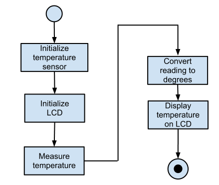
The algorithm is a step-by-step instruction, guideline or rule to perform some action or reach the solution for given problem. Flowchart is one of the way to represent algorithm graphically, where graphical elements like boxes, squares, circles, and arrows connecting them represent flow of control. Every element can represent on step in the instructions.
Simplified flowchart elements:
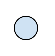
Start
End
Action or expression
Rectangle. Inside rectangle a name of the action, name of the sub-routine or short description can be written. Similar actions can be included into one general action.
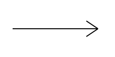
Sequence
Condition / Decision
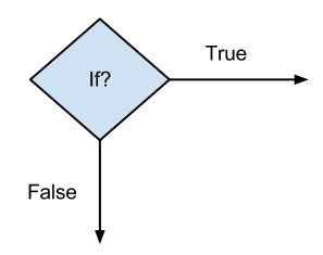
Diamond (rhombus). Inside diamond is a logical expression and in most cases two arrows are drawn out from diamond. One is when logical expression results True (Yes/1) and other when expression result is False (No/0). Always both arrows have to be labeled. In special case only one arrow can be used as output from diamond. The case is when logical expression can clearly result only one solution, e.g. True. This is the case where for example endless cycle is used in program code (e.g. while (true)).
Data exchange
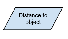
Trapezoid. Inside trapezoid a name or activity is described. In robotics it is usually used to communicate with sensors and user. For simplification also normal rectangle action can be used instead of trapezoid.
Examples
Drawing flowchart diagrams one can use common office suits like MS Word or MS Excel or OpenOffice/LibreOffice Writer or Calc but better results can be get by using special programs like MS Vision, OpenOffice/LibreOffice Draw, Google draw or some special diagram creating software.
Flowcharts describing microcontroller software usually do not have ends, instead whole main activity in an endless cycle. The exit condition of the endless cycle will never be true and therefore this is the case where condition block (diamond) can be represented only on exiting arrow. Condition it self can be notes simply True or 1. Creating diagrams it is important to keep in eye on the fact that if the program has forks, it can be done only through the diamond object. Junctions (two arrows are joining) can be described by special symbol, but in simple cases, one may simply have an arrow point to another arrow instead.
